Friday 11 August 2017

Salvaged Metabo HO 0882 Planer - It Lives!


Two years ago, I pulled this planer out of a skip ("dumpster" for any North American readers) near my gym. It was pretty dirty, but still in one piece, so I took it home and nervously spun it up with an RCD, just in case something shorted. To my great surprise, it actually worked. I figured some tradie on the nearby work site decided the bearings were shot and the blades were broken and it was cheaper to just buy a new one...or something.

As this was one of the more complicated things I've ever taken apart, it took me a a while to work out howto disassemble it. Much swearing and excessive force later, I had managed to remove the bearings (without a puller) and have it all in pieces in a bucket in my workshop. Since the disassembly was so traumatic, and I didn't really have a use for a power planer, there it stayed there, gathering dust, for 2 years.
I left the stator an the wires in the case
Dirty, dusty pieces

Recently I acquired (aka picked up off the curb) a bunch more free timber in the form of a discarded bed frame and require a fast way to remove the varnish. Since I don't really want to put the varnished timber through my main jointer/thicknesser, and I remembered that I still had "reassemble the free planer" on my todo list, I figured now was a good time to attempt the project.

I started by giving everything a half-hearted clean (I wasn't sure how well it was really going to work) and take stock of the situation. I found a PDF on a spare parts website that shows the exploded view of the planer - but the resolution was terrible and the model differed very slightly from the on I had - mostly in regards to a few screws and washers.

I had gotten really frustrated when taking it apart, as I couldn't find any videos or documentation of anyone doing the same thing. It made simple things like "how do I remove these pulleys" take ages for me to work out (just so you know, they aren't press fit, they are screwed on). As a result, I decided to try to film the reassembly for anyone else who may find this procedure useful in the future.


As a bonus, while reassembling the plane, I managed to establish a possible real reason the planer was thrown away. The locking button for the trigger doesn't seem to work anymore. I could imagine this would be quite annoying for anyone wanting to use it for extended periods of time (such as a tradie on a work site). For me, however, this is a minor inconvenience.

All up the project cost me the price of some new bearings (AUD$14.50) and some new blades (AUD$9.99).

Saturday 14 January 2017

Home Made Bandsaw

As I've mentioned in previous posts, I have been wanting to make Mattias Wandel's wooden bandsaw for a while. The whole process has been a great learning experience. In particular, I've developed an appreciation for how small mechanical changes can have a huge impact on performance.

So here it is:

It's *very* purple

I started this project with the aim to keep the cost low, primarily for the challenge, but I also like the idea of building something from second hand materials. My plan from the beginning was to use (free) pallet wood for the laminated pine frame. It took three pallets to get enough good timber after planing and thicknessing. Each board ended up being around 18.5mm thick. The plans call for at least 17mm so this worked out well.


3 of these bad boys


Rough timber from broken down pallets


After planing


Cut to size as outlined in the plans

One of the coolest things about this design is the laminated pine frame. By laminating the layers of relatively weak pine boards with the grain crossing the direction of the previous layers at the corners, you can build up a very strong, very stiff wooden frame. In order to ensure accurate alignment of the various components later in the build, it is important to make sure the frame has very little twist. I used the technique outlined by Matthias in his Bandsaw Mill video to do this. The flattest surface in my shop, big enough to do this, is my table saw table, so I used it as the reference surface for the first few layers of lamination. As per the suggestion in the plans I left off the base of the frame until after I attached the bottom wheel mount.


Layers 1 and 2 of the main beam


I ran out of clamps again


The finished frame (sans the base)

I had previously tried to find a good second hand motor without much luck. In the end, I deviated from my "do it super cheap" plan and bought a reasonably priced new Krotec motor from ebay. The price (including shipping) for a brand new 1.5 HP motor ended up being less than AUD $150.


Specs!
Having not had much experience actually using a bandsaw, I was unsure how fast to run it. I did a bit of research on similar sized bandsaws. The Jet JWBS-16B for example is a 16 inch bandsaw that runs at 3000 SFPM (around 15.24 m/s). However on Marius Hornberger's Bandsaw wheel upgrade video, he mentions that he prefers his faster blade speed of 21 m/s (about 4134 SFPM). My plan was to settle somewhere between these two extremes and I created a spreadsheet to determine my final pulley sizes. I already had a pulley from the junk motor that fit on the shaft of the new motor, so I decide to base my design around that. In the end, after a few mishaps that resulted in my drive wheel pulley being smaller than intended (around 23cm diameter), I have ended up with a blade speed closer to the Jet JWBS-16B.

One of the other features of this design that makes it unique is that the wheels and drive pulley are turned true on the final bearings. The ball bearings are tightly pressure fit in Baltic Birch plywood flanges that are glued directly to the wooden wheels. The wheels can be any stable wood product that will not expand or contract like real wood does. MDF works great because it has a much more consistent density than plywood and is easier to balance later on in the build. It is heavy though so I followed Marius Hornberger's design and lightened them with large holes. These holes were incredibly difficult to cut on my under-powered drill press. It took many hours, but the hole pattern does look pretty cool once complete. 


Bearing in plywood flange


Bearing flanges attached to the MDF wheel


The next step was on of the most challenging for me. The design calls for you to mount a temporary pulley to each wheel and use the motor to turn the wheel like it's on a lathe. I had all sorts of trouble getting this to work correctly. When I first started, I only owned bench chisels. It is possible to turn the wheels using bench chisels but it definitely requires more skill and a strong hand to maintain control of the shorter tools. They also heat up easily and chip like crazy. I completed all of the MDF wheel profiles (again Marius Hornberger's design) using the bench chisels. 


Crown pulley profile on one of the wheels

My first tool rest worked ok for the MDF, but I was unable to turn the birch plywood pulley with this setup. As soon as I tried to do more than lightly graze the birch plywood with the chisel, it would gouge and I would get a very big fright as the whole setup was thrown out of alignment with the motor still running.


Tool rest Mk 1. Fail :(

After much frustration, I decided to make my birch plywood pulley blank as close to round as possible in the hope it would make turning easier. I removed the birch pulley and attached an MDF template that I cut with my router compass I then used the router table to trim the plywood flush to the template. Unfortunately it didn't make a huge distance. 


Oops. Bench chisels kept gouging the birch plywood pulley as I tried to turn the profile

I ended up emailing Matthias for help. He had the following advice:

The tool may catch if it's not well enough supported, and if it's aimed into the wood.  If you angle the chisel down a little bit, then the scraping action pushes it out of the wood instead of in.  Same for cutting on the side, chisel should be angled out of the wood slightly.


It's much more efficient turning with the chisel angled into the wood, but if your support is not solid enough, that doesn't work very well.

This all made a lot of sense, but I really thought my setup was quite stable. However as soon as I added a vertical support, things went much smoother. I also decided to buy a carbide turning tool. The longer handle made a huge difference for controlling the cut and the carbide is very sharp. The parting tool tip made cutting the pulley profile much easier as well - turning with a 6mm bench chisel is really quite challenging.


Tool Rest Mk2. Success!


Finished drive wheel and pulley


The next few months (I procrastinated a lot) were filled with working out how to mill the various hardwood and plywood components. For the hardwood, I used camphor laurel. It's cheap (because it's basically a weed) and I had picked up a few boards at the local woodworking show. It's a bit stringy when cutting it, but the shop smelt pretty nice for a while. 


Top and bottom wheel mounts

For the guide block I used some random hardwood I had picked up along the way. It felt pretty dense, so seemed like a good choice for the guides.


Top and bottom guide block assemblies

At this point in the build I realised I needed a way to test the bandsaw, but I didn't have a blade yet, and to be honest, was a bit too scared to put one on right away. I created a test "blade" using 2 opposing layers of blue masking tape. It worked quite well.


At some point I finally made it out to Carbatec to buy a cheap 10mm 6 tpi blade.


The new blade with trunion bar in place
Top wheel mount assembly
The next few weeks were then spent making all of the various enclosure pieces. I was originally going to modify the enclosure design, but by this point in the build, I didn't really have the drive to try to design something new. I just wanted to be done. 


Still so many more enclosure pieces to fabricate

Around this point in the build, I was quite busy with my day job and it felt like every time I came into the workshop I was making a huge mistake and then spending 2-3 times as long as it should have taken fixing it. One of the most annoying mistakes was the blade tensioning handle. It should have been pretty straight forward, but I forgot to take into account the top blade cover and it didn't fit. To reduce the size, I setup a quick jig on the table saw where I could spin the handle while slowly bringing the blade up next to it. In the end, this worked pretty well.


Bottom of the threaded rod had a lock nut spinning in a recess 

The next big disaster occurred sometime when cutting the trunions for the tilting table mechanism. There was a terrible noise and the blade started stalling. I quickly unplugged the machine and took it apart to find this:


Oops


One or two of the screws holding on the bottom pulley had vibrated loose and started tearing into the frame of the saw. Since I hadn't tuned up the saw yet, it was still running pretty rough and I think this is what caused the screws to come loose. I had to replace one of them with a higher gauge to make it tight again. I'm going to keep an eye on this going forwards, but my hope is that if I reduce the vibrations, it won't happen again.

Finally it was time to paint. I want to do some spraying for a future project and managed to pick up an Earlex HV5000 2 stage HVLP system on Gumtree for a pretty good price. It hadn't been used and cost about as much as a single stage system from Bunnings. I wanted to use the bandsaw finishing as a chance to practice some spraying.

For all of the painted pieces I did an undercoat with a water-based primer followed by an acrylic paint. It was about 400% humidity so it took a while for the paint to stop being tacky. I finished off the painted pieces with a coat of water based polyurethane and sprayed 3 coats of poly on the non-painted parts.


Once everything (finally) dried, I spent a weekend putting it all back together and tuning it up. I re-balanced the wheels and shimmed the crap out of various bits. In particular, my top wheel was out of plane with the bottom so I had to shim one of the L-shaped rails to pull the wheel forward on one side. Disappointingly after all this work, it still didn't pass the coin vibration test. It was definitely better, but not as good as I wanted it. I narrowed this down to the bottom half of the machine and plan to address it at a later date.

I also installed a cheap machine switch I got off eBay. Having never wired up a switch before, I spent a bit of time trying to work out what to do. In the end, it turned out to be really simple. A quick test with a multi-meter showed that the switch simply cuts the connection for all three power lines (live, neutral and ground).


The last piece to make was the metal blade guard. I bought a cheap cookie pan at a dollar store and cut it to size. As I don't have a sheet metal break, I clamped the sheet metal between some boards and used a mallet to percussively persuade the piece into shape. It, of course, wasn't the right size as I forgot to check the clearance with the top wheel (which I had shimmed earlier to bring the wheels into plane), so I just shimmed the blade guide to bring it forward as well.


Finally, the saw is more or less done. I suspect I'll be reworking some things over the next few months until I'm happy with it. In particular, the vibration issues are really quite annoying and I think they are affecting the cut quality quite a bit. It's difficult to tell because my skills with the bandsaw are also quite poor. I need to mess around and practice a bit more until I get the feel for things.

I have a couple of small logs that I have been waiting to cut up, so I started breaking these up with the finished saw. I was still using the 6 TPI blade - which is not really appropriate for this work - but it seemed to work ok, I just had to cut very slowly.

Finally get to see the grain inside!

Tuesday 3 May 2016

Router Table - Part 3: Bonus Upgrade!

Wheeled Cabinet with storage


My sister and I had some days off at the same time and she volunteered to help me get started on the cabinet for the router table. We began by roughing out the design on some scrap paper. The plan was to have a big drawer at the bottom to store all of my power hand tools and tool cases. The top drawer would be a lot shallower and used for smaller tools and accessories. Most of this stuff was cluttering my workbench and the floor, so I was keen to get them stored away neatly.

We used 18 mm MDF for the sides and drawer fronts and 16 mm MDF for pretty much everything else. I had bought some 12 mm particle board to make my tool wall, so we used that for the base. It didn't need to be strong, it just had to provide some additional rigidity.

We cut everything out using the Scheppach track saw and cut rebates for the base and top bracing using the router table itself.


Some glue and a whole bunch of screws later, I had a cabinet. I added two 70 mm locking swivel castors at the front and two fixed castors at the back. As you can see, I managed to put it to use right away.

Keeping the dust out


The project stayed this way for a few weeks. Once I got my new table saw *gasp* I decided that making some drawers for the cabinet would be a good first project.

The drawers are a basic construction. The sides are attached to the front and back using butt joints, glue and screws. The 12 mm particle board bases were rebated, glued and nailed. I bought some heavy duty full extension slides to make it easy to access items in the back. The 18 mm MDF fronts were then glued and screwed into place with as little clearance as possible to keep dust out. This video by John Heisz really helped with understanding how to install the slides.


Tidying up the switch

Once the drawers were done, all that was needed to make the table functional again was to feed the female end of the switch through the table so that I could connect it to the router. I started by cutting a hole big enough for the connector.

I then chiselled out a ramp to provide enough clearance to feed the cord behind the plastic body of the switch.


The switch was then screwed back onto the router table, hiding the hole and keeping everything looking neat and tidy. The dangling cord is the male end to be connected to mains.


Finishing touches

I made some pulls based on something I saw John John Heisz make, and enclosed underneath the hole in the router table with a 30mm deep box to keep the dust out of the top drawer but provide enough clearance to lower the router full depth through the hold made previously. I used a technique I saw in one of Marius Hornberger's videos to make this box using simple 45 degree glued mitre joints for all edges since it didn't have to be very strong.

How does it perform?

For my current needs, it's good enough. Adjustment of the router height is fiddly as you have to open the top, rest it on something (like your forehead) and fiddle with the Makita's "fine adjustment" ring until you get things right. Fence adjustment generally involves clamping it down then tapping with a hammer to "micro" adjust the positioning.

Future improvements I plan to make include:

  1. Painting the cabinet to seal the MDF (which is easily affected by moisture)
  2. Dust collection
  3. Better adjustment mechanism for the fence
  4. Throwing it all away, buy a new router, and make something else that has a router lift :)

In the meantime, the table has been useful for more than just routing. It is my go-to flat surface for glue ups (my main work bench is usually too cluttered) and it is a good height for a table saw outfeed table when cutting large pieces. The castors make it super easy to move around my tiny space and the storage as well has been very useful as I try to adapt my single car garage into a functional workshop.


Wednesday 20 April 2016

Induction Motor Adventures

I have plans to make this bandsaw. Ever since I saw the video I've wanted to make it. Matthias Wandel's design is super simple, lightweight and made almost entirely out of wood.

About 6 months ago I bought the plans and have been collecting all the parts I need as cheaply as possible. The frame will be from pine pallets that I've salvaged. I have tried to acquire a second hand motor but - it's been a challenge.

I managed to find this 2HP single phase induction motor on Gumtree for $15.


The guy was in the middle of nowhere and, based on our limited interaction, a little eccentric. He was adamant that "It had barely been used. The only problem is it needs a new start capacitor". For $15, I decided it was worth giving it a go. 2HP would be pretty much perfect for my home-made bandsaw. So I let my significant other know that if she didn't hear from me in an hour to send the police to the crazy man's place, and set off to pick it up. He had mentioned his aggressive people-hating dogs. More than once.


Annoyingly, the motor didn't have a wiring diagram, so being the diligent engineer that I am, I took to the internets to work it out. I first cracked open the terminal/capacitor enclosure to work out what I was dealing with. There were two capacitors. So far so good.


Rather than trying to measure capacitance with my crappy $20 multimeter (and general lack of knowledge/skills about exactly how to do this), the plan was to determine where to attach my power lead to the terminals, then check that the motor starts to see if the start capacitor really was gone. Not wanting to mess with 240V AC without a little more understanding, I looked around for some information about how the motor should be wired up. I also bought a Residual Current Device to avoid excessive current draw once I was ready to give it a go.

All About Circuits had a great article that explained a standard capacitor run single phase induction motor circuit. Based on this information, I plotted out the known connections and drew a diagram to work out where the primary and starter coils should be. I came up with this:

The left side shows the coloured leads and the existing capacitor connections on the motor's terminal block. The picture on the right was how I thought the schematic mapped to the terminals.

With this information, I should be able to connect my multimeter to the two red wires and read continuity, and the two black wires and read continuity. I had about 6 ohms between the two red terminals, but no continuity between the black terminals, which is where I thought the starter winding should be.

At this point things were not looking good. It was time to crack open main motor enclosure. I wanted to confirm the centrifugal switch was fine, although I was pretty sure my understanding of the circuit was correct. At this point, I had nothing to lose anyway.

The enclose was a little rusty and required some percussive persuasion to remove the end bells. Lots of persuasion. After a few hours (and much swearing), I pulled out the rotor and was greeted by this:


I'm no expert, but I was pretty sure the black wiring was not a good sign. A few measurements with the multimeter and some careful inspection showed that the winding was indeed burnt out and was causing the lack of continuity between the black terminals.There were a number of solder blobs too, so it looked like someone (I'm looking at you crazy Gumtree guy) had tried to repair it in the past.

On the plus side, I managed to confirm that my understanding of the switch placement was correct. I also got to finally have a play with one after reading about how they work - which is always nice.

So...still motor-less - but at least I learned quite a bit.

Saturday 12 March 2016

Router Table - Part 2

A lot has happened in a year. A lot of tools were bought and I finally finished some projects that I had been "working on" for quite some time. In particular the Router Table. Here it is at approximately 70% done:

It's not quite finished but it's usable.

Making the table top

After a failed attempt to use the rest of the salvaged plywood from an old pallet, I decided to just use a manufactured material for the table top - MDF.

MDF is an engineered product and relatively flat which make a a great candidate for providing a reference surface for shaping timber on the router table. It does have a few downsides however:
  1. Potential health risks due to fine dust and binding agents (e.g. formaldehyde).
  2. Splits easily when using screws.
  3. Poor resistance to moisture.
Because of the first issue, it's important to have good dust extraction and to wear a respirator when working with MDF. I bought a basic respirator from Bunnings a while ago and use this whenever making fine dust - especially if it's MDF dust. I'm also working towards having dust collection at the source for most of my tools as this is by far the best way to ensure that you don't breathe in any harmful particles.

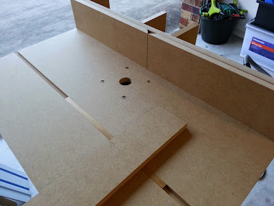
After cutting the MDF to the appropriate size, I lined up my router's base plate to mark the holes in the center of the table then drilled and countersunk the holes for the M5 machine screws. I had to buy longer screws in order to accommodate the additional thickness of the 18mm MDF. The router base plate is only about 5mm thick.


I made a simple jig and used my router and a guide bushing for cutting the recess for the 100 mm butt hinges.


I then used the same jig to make a similar recess on the table box itself and then attached the hinges to both pieces using screws.


The router was then secured to the bottom of the table with the M5 machine screws. I hadn't completely accounted for the depth of the router in my design so I had to make a recess in the bottom of the main box to allow the router to drop through. I would need to work around this later in order to keep any dust contained within the main box when using the router table. 


Making the fence

I had always planned on making a split fence in order to be able to joint boards using the router table. The split fence design also makes it easier to ensure that the router bit is as close to the fence as possible at all times. This improves dust collection and makes routing operations safer by providing more support to the work piece.

I didn't make any real plans for the fence and more or less made it up as I went along.

I cut two long pieces for the front and base of the fence using my recently acquired Scheppach CS-55 track saw. This was much faster than the previous approach of using a router to cut materials to size. I also cut out the vertical support pieces to keep the fence square, the 45 degree angled piece that would provide a dust collection port and the two front sliding fence pieces.


The pieces were glued and screwed together.


In order to cut the slots for the sliding front, I setup a temporary fence with the router installed in the table. I then made a wider slot for the bolt heads to sit in.


I had wanted to try making some knobs for a while so this seemed like a good chance to try it. I began by drilling five pilot holes in a piece of MDF. 


I Then used a 16 mm spade bit to bore out the outer holes.


The the whole knob was then cut out using a cheap hole cutting bit in my cordless drill. I made matching cut-outs in a thinner sheet of MDF and chiselled out a recess for the bolts in the thicker piece.


The thinner sheet of MDF was then used to cover the bolt.


The hole assembly was glued together and after a bit of sanding the finished knob looked pretty slick.


Not quite square

After assembling the fence I realised that a combination of poor alignment and bulging from screws in the MDF meant that the fence was not sitting 90 degrees to the table top. To fix this, I decided to plane down the base of the fence until It was as square as possible to the table. For obvious reasons, I had to remove the screws before doing this.


After a bit of fiddling around, I got it pretty much dead on.


For bonus points, I added a mitre slot and a really simple mitre gauge to the table. My plan is to just clamp down the fence for now. At some point I might try to add a slot or track system to make things easier.  


Finishing touches

To finish things off I attached the 4 of the 5 free Ikea style legs to the bottom of the main box with screws and painted the main box with a water based paint. The MDF was sealed using shellac and then waxed to provide a smooth low friction surface. I bought a switch from the local woodworking supply store and attached it to the outside.

Due to the hole in the bottom of the box, dust collection was not perfect. Also, the cord for the router had to be fed through this hole to reach the switch on the side of the box as the switch is actually for a Triton table and isn't really designed to be installed into something with walls as thick as my router table.


In part 3, I'll finish things off. The Ikea legs are temporary. The plan is to make a rolling cabinet with drawers for storing power tools and accessories.